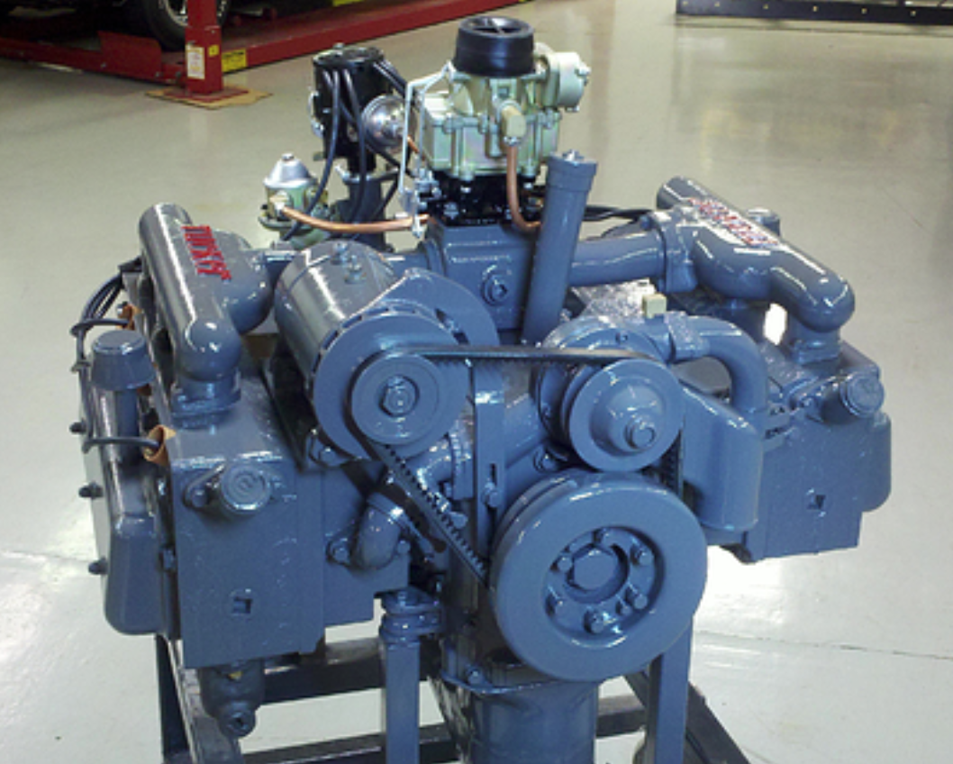
Tucker Tech Engine

Tucker Tech By Mark Lieberman TACA Technical Advisor
Tucker Tech is a series of articles that discuss the interesting and unique features of the Tucker automobile and it mechanical components.
The Tucker 335 Engine
Designed for aviation use, these 335 cubic inch, flat 6 cylinder, aluminum engines had a proven record of performance and durability. Manufactured by Aircooled Motors of Syracuse New York, these Franklin engines were available in a variety of configurations. They produced 2, 4 and 6 cylinder engines using the identical platform. Many of the engines shared components. These included pistons, connecting rods, bearings, cylinders, valves, lifters, pushrods, rocker arms, valve covers and more. They even had turbocharged versions of the 6 cylinder engine.
Ultimately, the engine chosen by Tucker for their car was the 6V4-178. It produced 178 horse power and 390 pound feet of torque. A great engine for sure, but not well suited for automotive use in its original configuration. Among the challenges in front of the engineers charged with converting the Franklin 6V4-178 engine into automotive use included fuel delivery, ignition, and engine cooling . In its original configuration, the Franklin engine was designed to operate under a consistent load, relatively low RPM (2400-3200 max) and maintain that RPM for extended periods of time. This is illustrated by the chart below.
You may find it interesting to know that in the Franklin 6V4-178 operators manual it states: If the engine is operated at over 3600 RPM, it must be “removed from service for overhaul, inspection and repair”.
In order to get this engine to operate like a car engine, several changes needed to be made.
Fuel Delivery:
They needed a carburetor with an accelerator pump that would allow for rapid acceleration at various speeds. They selected the Stromburg AAV-26, two barrel, down draft carburetor. This was jetted and slightly modified from its original configuration. It was mounted to an intake plenum that was heated by circulating liquid from the engine. Then a special intake manifold design was created. The proto-type was crafted from hand shaped and welded sheet metal. It incorporated an internal diffuser in order evenly distribute the air/fuel mixture to each cylinder. After the design was finalized, the intake manifolds would be produced from cast aluminum. A mechanical fuel pump driven by an eccentric on the distributor drive shaft and mounted to the distributor stand, provided fuel to the carburetor.
Ignition:
The Franklin engine utilized a magneto for spark control. This was impractical for automotive use. A conventional ignition distributor and coil would be needed. The first choice was an Autolite model 4203A. It was used by Hudson from 1940-1947 and was readily available. They machined a hole and mounting perch on the top of the aluminum engine block and cast a distributor stand to mount it on. The distributor was driven by a slotted metal rod that was linked to the oil pump drive gear. The modifications it required were limited to bracketry and advance curve adjustments. These were used on the early engines, prior to the identification prefix of 335-. After a short time, this distributor was changed in favor of another model from Autolite specifically for this application. The new distributor allowed for the spark plug wires to exit the side of the cap, thus preventing the wires from rubbing on the underside of the parcel shelf. It also had a more desirable advance curve for improved engine performance. When this switch was made, a shorter distributor stand was cast to provide more clearance and compact design.
Engine Cooling:
Tucker must have attempted to use the Franklin engine in a modified Air-cooled version. The example of this is pictured here:
Apparently that approach failed as no further development of this took place. Liquid cooling was the answer. In order to make that work, the previous cylinders with cooling fins were discarded. An aluminum casting that incorporated 3 cylinders and cooling passages for liquid was constructed. A cylinder head also incorporating 3 cylinders and cooling passages for the circulation of liquid was also fabricated. Furthermore they had to modify the timing cover to incorporate a housing for the water pump. This pump is driven by a large gauge V belt that triangulates between the generator and the crankshaft pulley.
Each of these modifications were engineered and implemented in a very short time frame and running changes were the order of the day. As feedback from the guys building the cars and those testing them came in, changes and improvements were made. There is evidence of this happening right through the end of production.
Additional changes were made and even more were planned but were cut short from being implemented due to the untimely closure of the company. I will address more of these in future articles.


