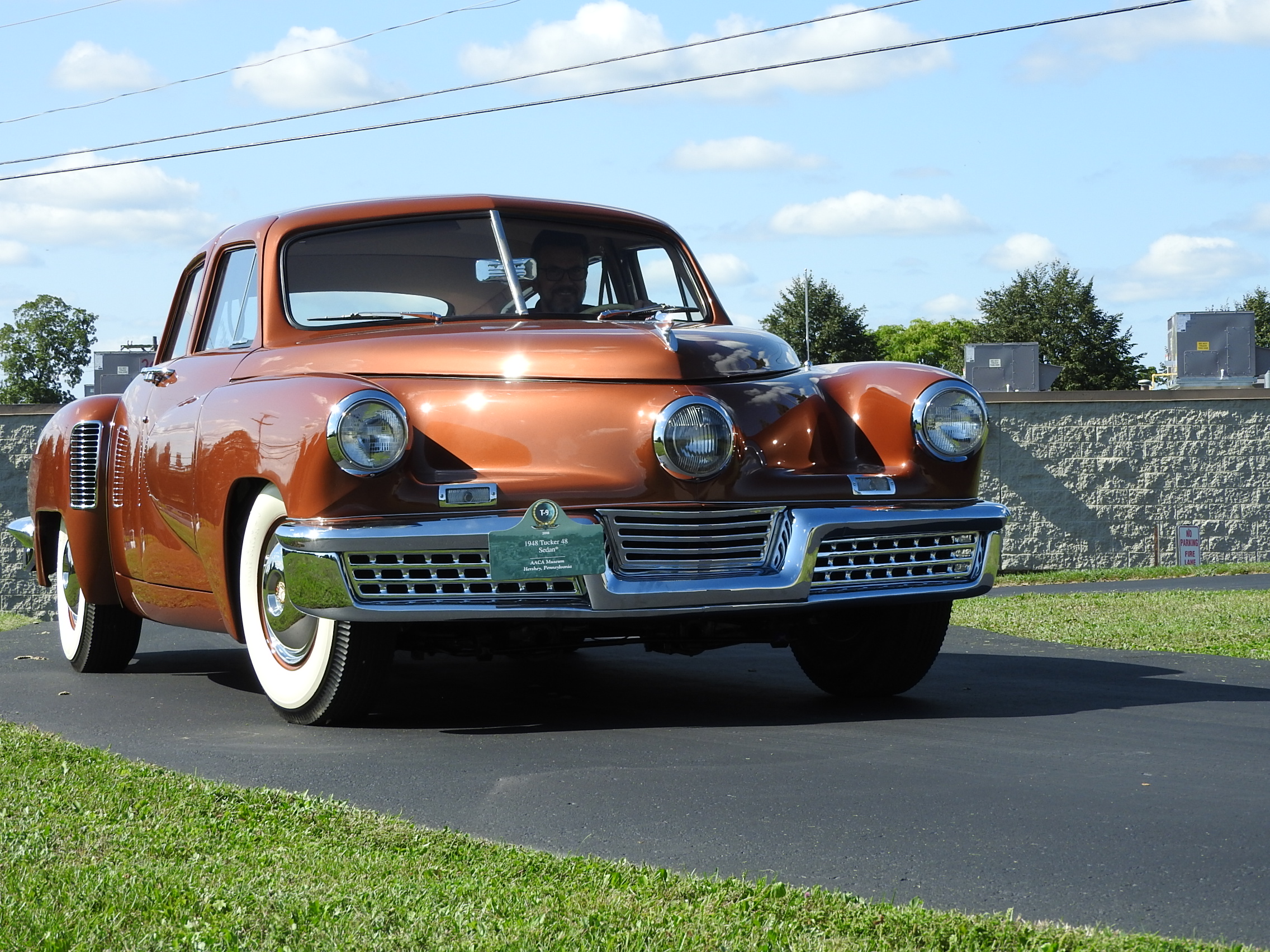
Reviving and Driving Tucker #1026 Part 2
Reviving and Driving Tucker #1026
Part 2
By Mark Lieberman
Continued from our last publication:
To safely extract the fuel tank for cleaning and sealing, we needed to carefully remove the entire front clip. On a tucker this includes the luggage tub as well. Our team carefully taped off the edges to protect the paint and unbolted the bumper, fenders and tub. We slowly removed each piece and exposed the fuel tank. At this point, extracting the tank was as simple as removing the straps…and out it came. We sent the tank to a specialist to boil it out and coat it for long term protection.
Now we move our focus to the suspension. The original Torsilastic tubes were still in place and had long since perished. This was a common issue for the Tucker suspension. Tucker had 3 suppliers of these tubes, Goodyear, Firestone and United States Rubber. They had issues with these from the very beginning. The technology for bonding the rubber to the steel was not very advanced at this stage and they experienced frequent suspension settling or collapse.
The concept was quite advanced. Replace steel springs with a compact rubber torsion bar that would provide a smoother ride and have limited adjustability. The first attempted applications were the test chassis and the Tin Goose. They used 2, small rubber impregnated pucks on each upper control arm. These proved insufficient to suspend the car under stress. From there they changed their design to incorporate the use of a 12.5” tube to suspend each corner of the car. This was first employed on Tucker #1001. These were comprised of a steel inner tube bonded to molded rubber that was in turn bonded to an outer steel tube. The outer tube was clamped to the chassis and the inner tube was connected to the control arm (front) or trailing arm (rear). These performed much better than the puck design. The major problem they faced now was unpredictable handling due to a complicated series of linkage connecting the tube to the front suspension. Ultimately, they would utilize a rubber shear plate design, for the front of the car instead of the rubber torsion bar for cars #1002 – #1025. This significantly improved the handling but provided no adjustability and was prone to rubber bond failure as well. Beginning with Tucker #1026, a new, much simpler design would allow them to utilize the rubber torsion bars in the front also. Now they had the adjustability they desired but would still need to improve the handling. This would next be addressed on some of the cars at the Indiana Motor Speedway high speed trials. Some of those cars, such as #1029 (Preston’s personal car) received anti-sway bars and stability bars.
To correct the collapsed suspension on #1026, we removed the original Torsilastic tubes. The front tubes unbolt from the lower control arms and slide out of their retaining clamps. We replaced them with new units of our own manufacture that duplicate the appearance of the originals and perform to the original specification requirements. A threaded hole is machined in the retaining clamp and located to accept a locking pin. Once these are in place, its just a matter of sliding the new tubes in place and adjusting them to the correct ride height. The rear Torsilastic units are more complicated. The center tube of these are welded to the rear trailing arms. To remove the original units we had to machine the weld off and re-center the hole to accept the replacement tubes. A special jig is employed to insure proper alignment. In addition, the new units must be kept cool while they are welded in place to protect the rubber from overheating. Once that is complete, locking pin holes are machined and threaded and the new units can be installed. Before final assembly could be completed, we inspected the rear axle shafts for cracks (another common issue) and replaced all of the axle bearings and seals. This would insure proper and smooth operation. Now that all 4 new Torsilastic tubes are in place, #1026 is standing tall. Final ride height adjustments will be made after the front clip has been re-installed.
Next, we move our attention to the brakes. The master cylinder was dry and each of the wheel cylinders were locked solid with corrosion. The brake shoes were old and cracked but not terribly warn. We elected to replace them along with the bearings and seals. In addition, the master cylinder, wheel cylinders and brake lines would all require replacement. We also observed that there was an additional brake line teed from the rear brakes to a hydraulic cylinder mounted on the upper section of the Tuckermatic Transmission. When the brakes were applied it would depress a rod that went into the transmission. Further research in the Cammack archives with the help of Mike and Sean Tucker revealed original blue prints for R1, R2 and R3 Tuckermatic Transmissions. These prints gave us a clear look at the inner working of the transmission. In addition, we learned from Stan Gilliland that this car had a 3rd pedal on the floor, near the seat bottom that was depressed with the left heal of the driver. I have no idea how anyone over 5’4” could actually do this. We located the mounting holes for this and the remnants of a bracket. We don’t know if this was hydraulically or cable actuated because no blueprints have been located for this as of yet. Stan informed us that depressing the pedal would stop the external torque converter from spinning, allowing the driver to shift from forward to reverse with the engine running. That must have been what the previous mechanic was trying to accomplish with the added line off of the rear brakes. We determined that this modification created an unsafe operating condition. It was depleting the liquid displacement capacity of the master cylinder due to the additional volume needed to fill and expand the additional wheel cylinder. We omitted it from the brake system and ran a series of experiments with a separate source of actuation. I’ll detail that for you later in the article. At this point we were able to complete the rebuild of the braking system and #1026 was now able to safely stop.
When the Tucker brake system is working correctly, its very effective. Under hard braking conditions, the weight is shifted forward as a result of the rear suspension design. This allows the front brakes to grab harder and reduce the chance of the rear wheels locking up. This combination of factors resulted in reduced stopping distances compared to other vehicles of the time.
Our next task was to wake up the 335 engine. After draining and inspecting all of the fluids, we were very encouraged. Everything looked pretty good. Fresh spark plugs, points and condenser began the process. The carburetor was removed and rebuilt. The mechanical fuel pump was absent and replaced with an electric pump. This was a common change for many of these cars. It was a long distance from the fuel tank to the mechanical pump and this could be problematic from time to time, so in many cases the electric replacement was employed. We replaced the pump, as the previous unit was crispy like burnt toast. Fresh oil and coolant were installed and we carefully rotated the engine by hand for a few revolutions. Everything looked, sounded and felt very good. We next checked the fluids in the transmission (we would attend to this further in the process) they looked good in the body of the trans. A few deteriorated wires were replaced and a fresh battery was installed. Now we could check the electrical system. Lights, turn signals and gauges we all checked. Everything powered up and looked good. Before the engine could be fired up we reinstalled the freshly reconditioned fuel tank, installed a fuel line, new fuel tank sending unit and re-fitted the front clip. Everything went together beautifully. We then replaced the oil pressure sending unit. We are now ready to bring this engine to life!


